Solid Edge
CAD Co-Pilot is an AI chat assistant built into Solid Edge as an add-in. Describe what you want in plain language and CoPilot carries out the work in your open document — sketches, features, drafts, assemblies, sheet metal and simulation — reporting each step as it goes.
Installation
Run the Solid Edge CAD Co-Pilot MSI installer (the per-CAD installer for Solid Edge). Close Solid Edge before installing. After the installer finishes, restart Solid Edge; the AI Co-Pilot ribbon tab appears once Solid Edge has restarted.
Where to find CoPilot
CoPilot appears as an AI Co-Pilot ribbon tab with two buttons: Open CoPilot and Help. Click Open CoPilot to start the chat, which opens as a floating window you can re-open at any time.

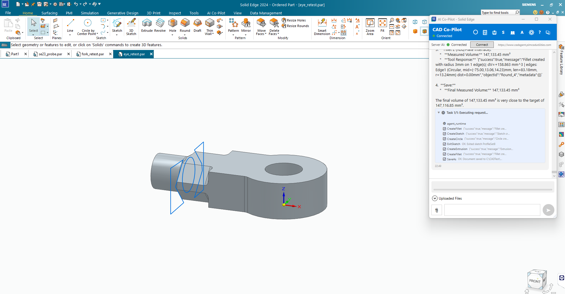
Your first prompts
Then move on to the worked examples in Part Modeling.
Three Solid Edge-specific habits
Create a sheet metal part as a sheet metal part. Solid Edge needs the document to be of the sheet metal type before tabs and flanges will work. Say “create a new sheet metal part” rather than creating an ordinary part first.
Use a tapped hole for an internal thread. That is the native route in Solid Edge and it is more reliable than adding a separate thread feature to a plain hole.
Measure an assembly by bounding box and component count, not by volume. Solid Edge's assembly-level volume query is not a dependable number; the bounding box is.
What CoPilot can do in Solid Edge
- Modelling — sketches, extrude (protrusion and cut), revolve, sweep, loft, round, chamfer, hole, thread, thin-wall, draft, boolean, split, patterns, mirrors, reference planes and axes. See Part Modeling.
- Surfaces — offset, extend, trim, thicken.
- Sheet metal — base tab, edge and contour flanges, bends, hems, jogs, corner breaks, flat pattern and DXF export.
- Assemblies — insert, relate, replace, suppress, BOM export and import, interference checks, cloning through Revision Manager. See Assemblies.
- Draft (drawings) — sheets, views, dimensions with automatic value checking, notes, balloons, parts lists, centre marks, GD&T, weld and surface-finish symbols. See Drawings.
- Family members — family of parts, family of assemblies, and assembly design configurations.
- Variables — Solid Edge variables and formulas: list, read, create, change, import and export.
- Simulation — Solid Edge Simulation. See below and Simulation & FEA.
- Nesting — the built-in Nest utility when a Premium licence is present, otherwise CoPilot's own nesting engine.
- Teamcenter — through the Tc4SE add-in, when Solid Edge is running in managed mode.
Family members
Variables and formulas
Solid Edge variables carry units, and a formula string is written in display units. Ask CoPilot to report the unit alongside the value whenever a number looks a thousand times too large or small.
Macros
Solid Edge macro recording (.bas) is supported: CoPilot can start and stop the recorder, run an existing macro, and store macros in the Automation Hub with named parameters.
CoPilot's own recorded macros work here too — see Macros.
Simulation in Solid Edge
Solid Edge Simulation is available and covers the four study types most people need:
- Linear static
- Frequency (modal)
- Thermal
- Buckling
Data management
Solid Edge connects to Teamcenter through the Tc4SE add-in, and CoPilot uses that connection — check in and out, search, read and write properties, drive lifecycle transitions and export BOMs.
Things that are not available on Solid Edge
- Exploded views from chat.
- 2D spline creation, datum point creation, sketch offset and trim, and planar surfaces from boundary curves.
- Face divide, face delete, face replace and curve projection.
- Coaxial and insert assembly constraints as separate operations, and grounding a component from chat — use a concentric relation, which works well.
- Deleting a feature by name. A cut can be undone; a protrusion generally has to be repaired geometrically — add the missing material or cut the extra. Take a checkpoint before a risky sequence.
- Auto-numbering when cloning an assembly; prefix, suffix, regular-expression and per-component renaming all work.
- Mould parting surfaces, shutoff surfaces, mould bases, runners and cooling channels return written guidance rather than geometry — Solid Edge has no API for them. Draft analysis, parting lines and core/cavity split do work.
- Weld, surface-finish and GD&T symbols are supported but with a narrower set of types than the other CAD systems. If a specific symbol type is refused, that is why.
- CAM setup and toolpath generation are not available in any CAD system yet.