Industry use cases: design rules turned into models
A use case here starts with a designer describing an envelope — the overall size, which holes go where, what material — and leaving the dimensions that a design rule actually governs (an edge distance, a fillet radius, a wall thickness, a bolt pitch) for CoPilot to work out from the design-rule corpus that ships with the product. CoPilot finds the applicable rule, quotes its id and source, builds the part with the rule’s own numbers, saves it, takes a picture of the result, and reports back what the CAD system actually measured — not what was asked for. Every example below was actually run, once each, on all four supported CAD systems — SOLIDWORKS, Inventor, NX and Solid Edge — through the same kind of conversation covered in Examples, so the numbers and pictures on this page are what came back, not a mockup.
Each request below is shown as typed, but it is really the middle of a slightly longer message: every one actually opened with a sentence naming the designer’s industry and asking CoPilot to use the shipped design-rule corpus for every dimension left to the rules, quoting the rule id and source for each, and closed with the same few housekeeping instructions — build from a new part, set an isometric view, save the part and a picture of it, and report back what the CAD actually measured (solid count, volume, bounding box) rather than what was asked for. Only the paragraph shown in each box below — the part itself — changed from one use case to the next.
Each table below is one recorded run per CAD system, not an average or a certified result. The rule-governed dimensions — and therefore the measured volume — can differ between runs and between CAD systems, because it is the AI model that makes the engineering choice from the rule each time, not a fixed formula. Where two CAD systems chose the same value, their measured volumes agree, sometimes to many decimal places, which is the point of reading the number back from the model rather than taking the reply on trust. Where a table shows CAD systems with different volumes, a short note says which choice each one made — not which one is right.
1. Aerospace — a machined fitting plate
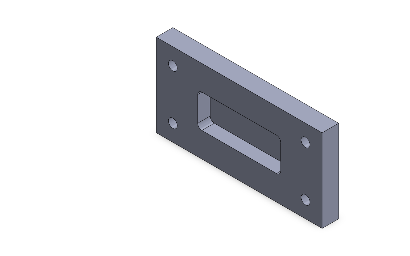
The situation. A machined aluminium fitting plate for an aircraft structure needs its fastener holes placed at the minimum legal edge distance and its weight-saving pocket corners radiused correctly for the mill that will cut it.
What happens. CoPilot cites AE-FJ-002 (fastener edge distance, nominal 2×D including the position-tolerance allowance, MMPDS-2026) to place the four M6 holes 12 mm from each edge, and MC-MILL-001 (internal pocket-corner radius versus depth, aluminium) to round the pocket’s vertical corners to 3 mm. All four CAD systems landed on exactly the same numbers and the same measured volume — the closed-form geometry for this part comes out to the same figure to the last digit.
| CAD system | Measured volume | Note |
|---|---|---|
| SOLIDWORKS 2024 | 71,965.375 mm³ | |
| Inventor 2025 | 71,965.375 mm³ | |
| NX 2306 | 71,965.375 mm³ | |
| Solid Edge 2024 | 71,965.375 mm³ |
2. Heavy machinery — a lifting lug
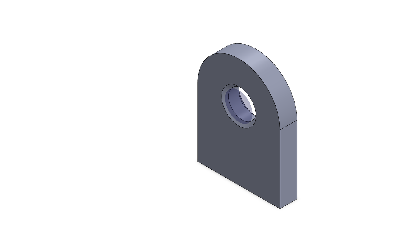
The situation. A steel lifting lug for a statically loaded crane lift has one job the rules cannot compromise on: the pin hole must sit far enough from the plate edge that the lug cannot shear out under load.
What happens. The corpus states the lug edge-distance rule two ways — HM-LUG-001 (centre-to-edge distance, at least 1.5× the hole diameter) and HM-LUG-007 (the net ligament from the hole’s own edge to the plate edge, at least 1.0× the hole diameter) — and is now explicit that the two are the same requirement stated two ways: satisfying one satisfies the other. The dictated 50 mm pin hole fails both forms, so every CAD reduces it to the same 40 mm hole, and all four kernels agree on the resulting volume to within a millionth of a cubic millimetre.
| CAD system | Measured volume | Note |
|---|---|---|
| SOLIDWORKS 2024 | 406,552.35 mm³ | 40 mm pin hole |
| Inventor 2025 | 406,552.35 mm³ | 40 mm pin hole |
| NX 2306 | 406,552.35 mm³ | 40 mm pin hole |
| Solid Edge 2024 | 406,552.35 mm³ | 40 mm pin hole |
3. Marine and shipbuilding — a deck plate opening
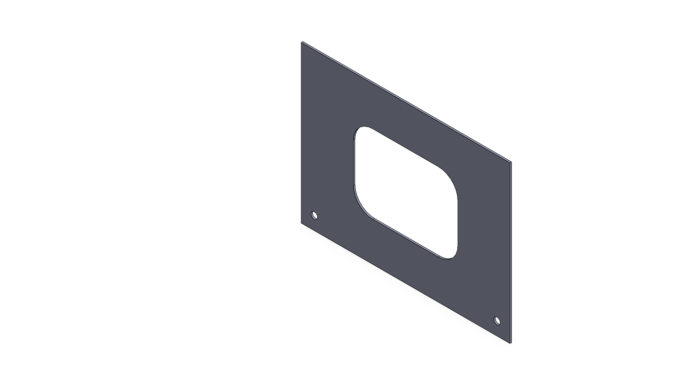
The situation. A steel deck plate needs a survey-access manhole sized and radiused to class rules, plus drain holes at the minimum legal diameter.
What happens. MO-ACC-001 (minimum clear opening for survey access) governs the manhole. In these recorded runs, the manhole’s footprint and corner radius were not the same choice on every CAD: two systems built an 800×600 mm opening with 150 mm corners, one built the same 800×600 mm opening with 100 mm corners, and one built a 600×600 mm opening with 100 mm corners — the table below is each of those, read back from the model.
| CAD system | Measured volume | Note |
|---|---|---|
| SOLIDWORKS 2024 | 17,464,646.09 mm³ | 800 × 600 mm manhole, 150 mm corners |
| Inventor 2025 | 18,775,884.99 mm³ | 600 × 600 mm manhole, 100 mm corners |
| NX 2306 | 17,464,646.09 mm³ | 800 × 600 mm manhole, 150 mm corners |
| Solid Edge 2024 | 17,335,884.99 mm³ | 800 × 600 mm manhole, 100 mm corners |
4. Sheet-metal fabrication — a bent bracket
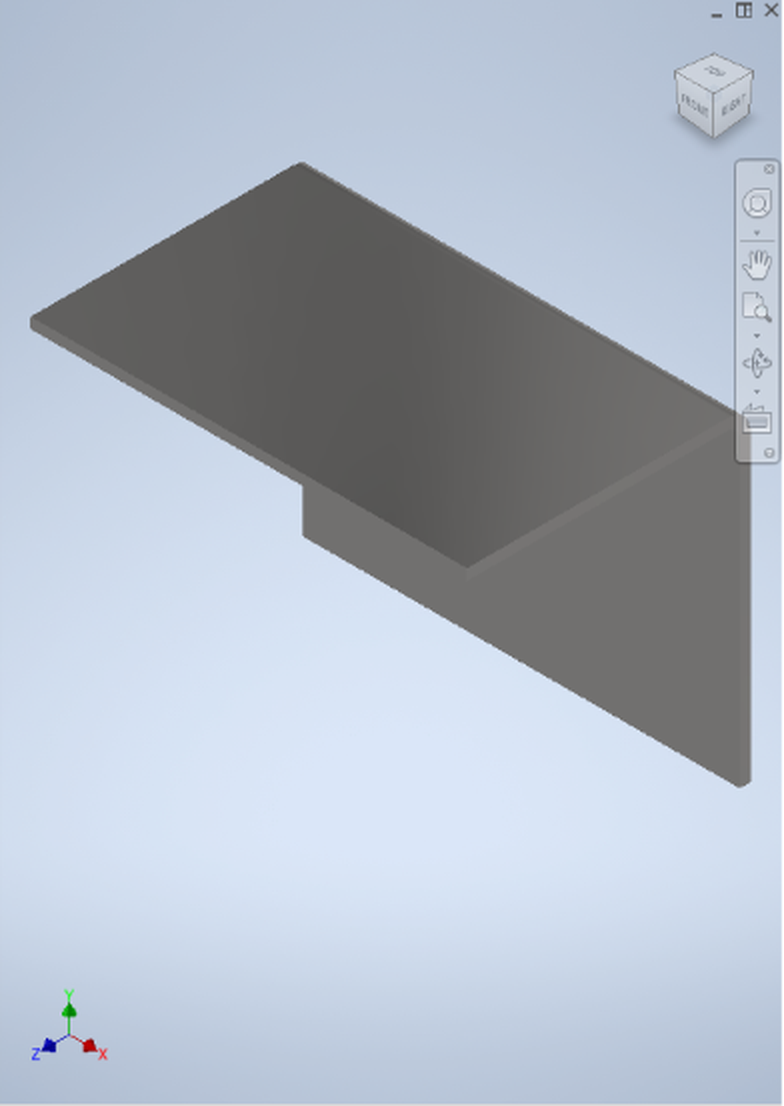
The situation. An L-bracket has to be a true sheet-metal part that flattens back out, with its bend radius, hole-to-bend clearance and flange length all checked against the mild-steel rules for its thickness.
What happens. SM-BEND-001 (minimum inside bend radius, mild steel) sets the bend to 2 mm; SM-HOLE-001 (round hole clear of the bend deformation zone) keeps the two base-flange holes at least 6 mm off the bend line; SM-FLNG-001/SM-FLNG-002 check the 50 mm upright flange against the minimum length a press-brake can actually form.
| CAD system | Measured volume | Note |
|---|---|---|
| Inventor 2025 | 17,280.88 mm³ | |
| Solid Edge 2024 | 17,280.885 mm³ |
5. Casting — a bearing housing
The situation. A sand-cast bearing housing needs its minimum wall, its fillet radii and its pattern draft angle all set from the casting rules for grey iron rather than guessed.
What happens. CF-WALL-001 (minimum castable wall thickness, grey iron, machine-moulded sand) sets the base plate to 4 mm; CF-FILLET-001 (internal fillet radius, sand casting) sets the boss-to-base fillet to 3 mm; CF-DRAFT-001 (minimum draft on sand-cast surfaces) sets the boss’s pattern draft to 1.0°. All four CAD systems built this one closely together.
| CAD system | Measured volume | Note |
|---|---|---|
| SOLIDWORKS 2024 | 218,975.72 mm³ | |
| Inventor 2025 | 218,975.16 mm³ | |
| NX 2306 | 219,002.68 mm³ | |
| Solid Edge 2024 | 217,936.18 mm³ |
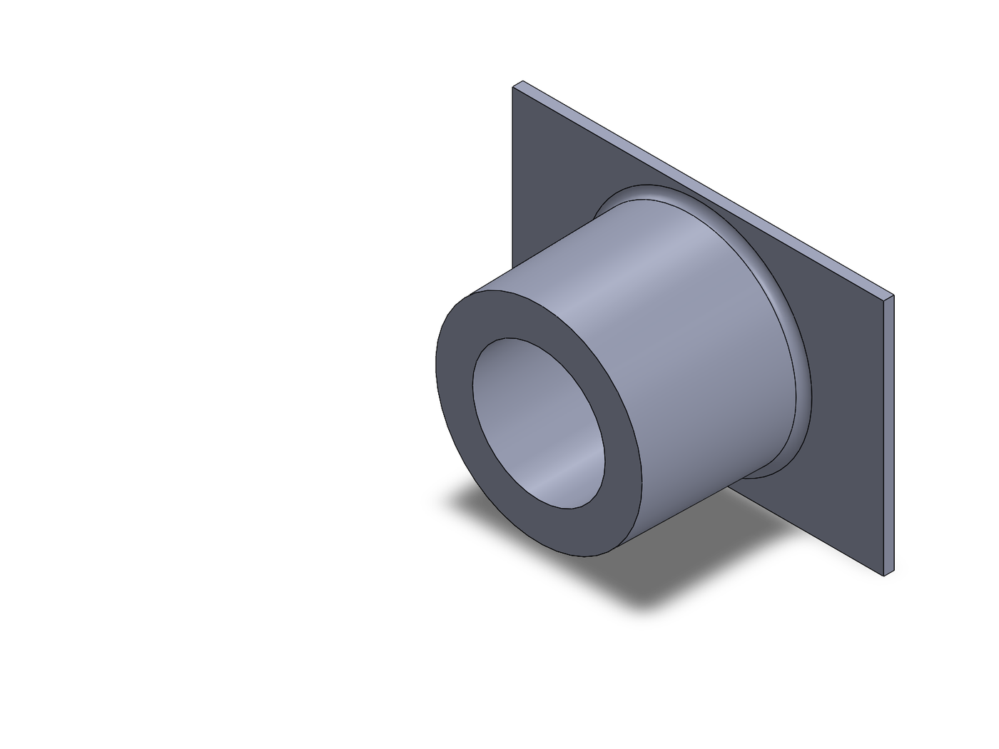
6. Machining — a pocketed block
The situation. A milled aluminium block’s rectangular pocket has to go as deep as its own cutting tool allows, with its corners radiused for that cutter, and its four tapped pilot holes cut to the depth a tap can actually use.
What happens. A family of machining rules bounds the pocket at 25 mm deep for the stated 10 mm cutter, leaving the floor thickness the rules require; MC-THRD-002 (thread engagement beyond the strength plateau, aluminium, 2.5×D) caps the M6 tapped-hole depth at 15 mm — deeper adds tap-breakage risk with no strength gain once the bolt itself is the weaker part. Two CADs report a volume matching the closed-form geometry exactly; the other two report about 350 mm³ more, which turns out to be the drill’s own conical tip below the nominal hole depth — a real detail two of the four sessions modelled and two treated as a flat-bottomed hole.
| CAD system | Measured volume | Note |
|---|---|---|
| SOLIDWORKS 2024 | 140,182.52 mm³ | closed-form exact |
| Inventor 2025 | 140,535.90 mm³ | includes the drill-point tip |
| NX 2306 | 140,535.896 mm³ | includes the drill-point tip |
| Solid Edge 2024 | 140,575.22 mm³ | closed-form exact |
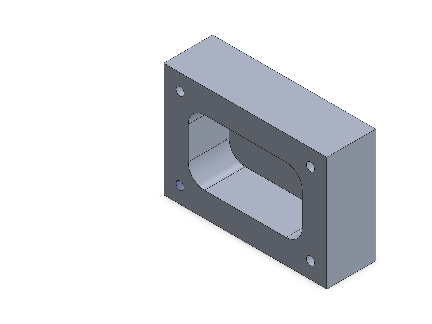
7. Plastics and injection moulding — a moulded cover
The situation. An ABS cover’s wall, its internal stiffening ribs and its draft angle all have to respect what the resin can actually mould without sinking, warping or sticking in the tool.
What happens. IM-WALL-001 gives the mouldability floor for ABS; two of these runs used the 2.5 mm wall the request itself gives as a fallback, one used 2.0 mm, still above IM-WALL-001’s own 1.15 mm minimum. IM-RIB-001 (rib thickness relative to wall) and IM-DRAFT-001 (minimum draft for an untextured face) size the ribs and the 0.5° draft.
| CAD system | Measured volume | Note |
|---|---|---|
| Inventor 2025 | 50,567.40 mm³ | wall 2.5 mm |
| NX 2306 | 40,865.29 mm³ | wall 2.0 mm |
| Solid Edge 2024 | 52,068.01 mm³ | wall 2.5 mm |
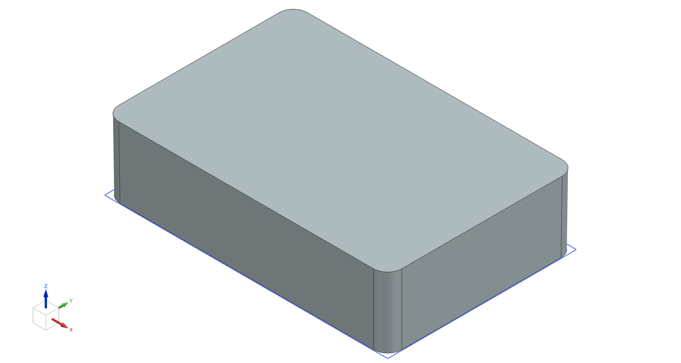
8. Pressure equipment — a vessel head and shell
The situation. A pressure-vessel end has to be one revolved solid — a cylindrical shell closed by a semi-ellipsoidal head — with its nozzle placed far enough from the head-to-shell weld seam that the two welds’ heat-affected zones don’t overlap.
What happens. The corpus’s shell-and-head design guidance favours a 2:1 semi-ellipsoidal head over a flat cover at this diameter and pressure class; PV-NOZZ-006 (clearance from a nozzle weld toe to the head-to-shell seam, at least the larger of 50 mm or 3× the wall thickness) is satisfied with the nozzle placed 80 mm from the joint. This is the most geometrically complex part in the set — a revolved shell plus head, minus a radial hole — and it is also the tightest agreement: four different CAD kernels land within three-hundredths of a percent of each other.
| CAD system | Measured volume | Note |
|---|---|---|
| SOLIDWORKS 2024 | 9,650,200.25 mm³ | |
| Inventor 2025 | 9,649,637.96 mm³ | |
| NX 2306 | 9,650,206.70 mm³ | |
| Solid Edge 2024 | 9,647,813.74 mm³ |
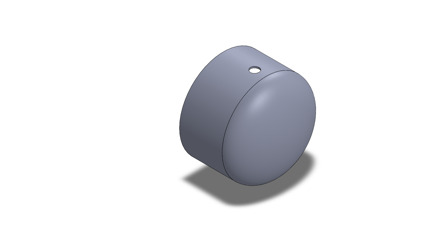
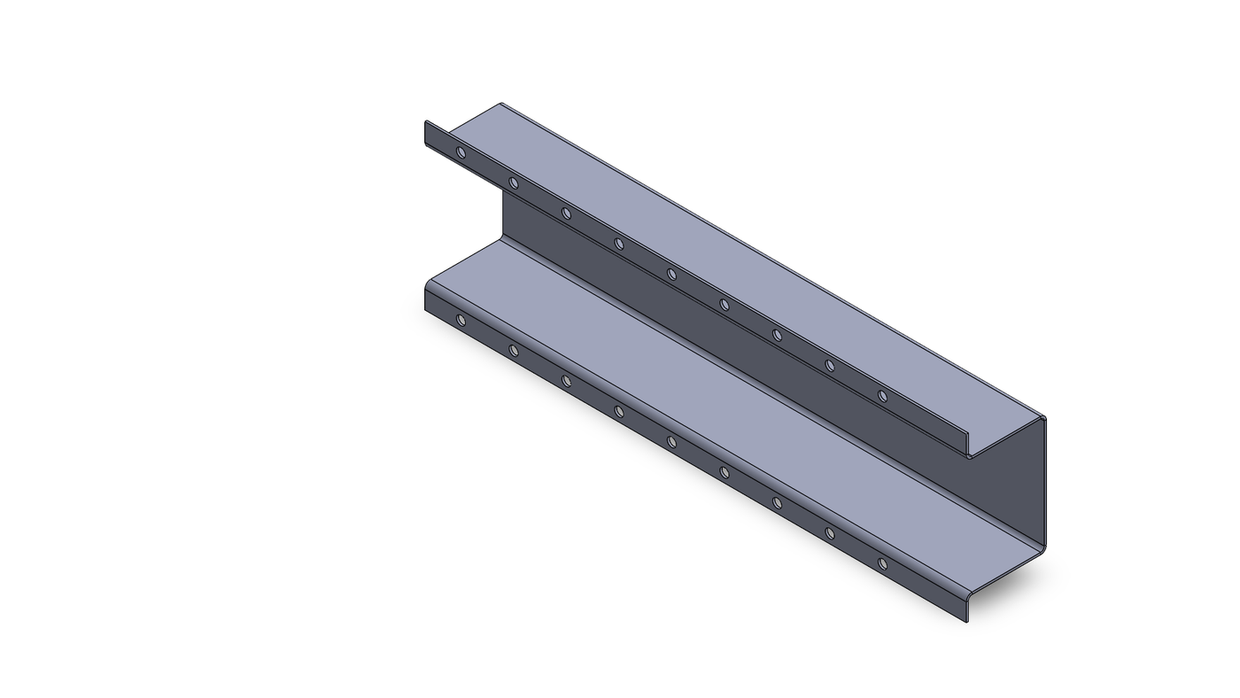
9. Automotive and rail — a spot-weld channel
The situation. A hat-section steel channel’s spot-weld flanges have to be wide enough for the welding gun’s electrode to sit clear of the bend, and its weld-marker holes have to be pitched far enough apart that one weld doesn’t shunt current away from the next.
What happens. AR-JOIN-001 (minimum spot-weld flange width) sets each flange to 12 mm on every CAD here; AR-JOIN-004 (spot-weld pitch, the shunting limit) computes to 29.2 mm on 1.2 mm steel — one of these runs rounds that to 30 mm instead.
| CAD system | Measured volume | Note |
|---|---|---|
| SOLIDWORKS 2024 | 61,616.95 mm³ | pitch 29.2 mm |
| Inventor 2025 | 57,008.95 mm³ | pitch rounded to 30 mm |
| NX 2306 | 64,255.56 mm³ | pitch 29.2 mm |
| Solid Edge 2024 | 58,568.76 mm³ | pitch 29.2 mm |
10. Medical devices — a surgical instrument handle
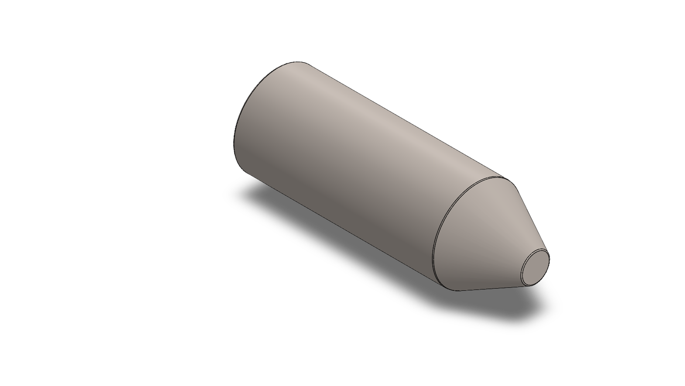
The situation. A reusable stainless-steel instrument handle needs a grip diameter in the usable ergonomic range and no crevice anywhere — every corner, inside and out, cleanable and every edge broken.
What happens. The shipped corpus has no medical-devices vertical, but it does now have DM-HAND-006, a general hand-grip-diameter rule (30–45 mm); either way, every CAD here lands on the same midpoint the request itself gives, 37.5 mm, with a 1.0 mm cleanability radius on every internal and external corner and a 0.5 mm sharp-edge break at both ends.
| CAD system | Measured volume | Note |
|---|---|---|
| SOLIDWORKS 2024 | 106,963.83 mm³ | |
| Inventor 2025 | 106,963.83 mm³ | |
| NX 2306 | 96,682.20 mm³ | same 37.5 mm diameter, a different measured volume |
| Solid Edge 2024 | 106,963.83 mm³ |
11. Electronics enclosures — a sealed enclosure base
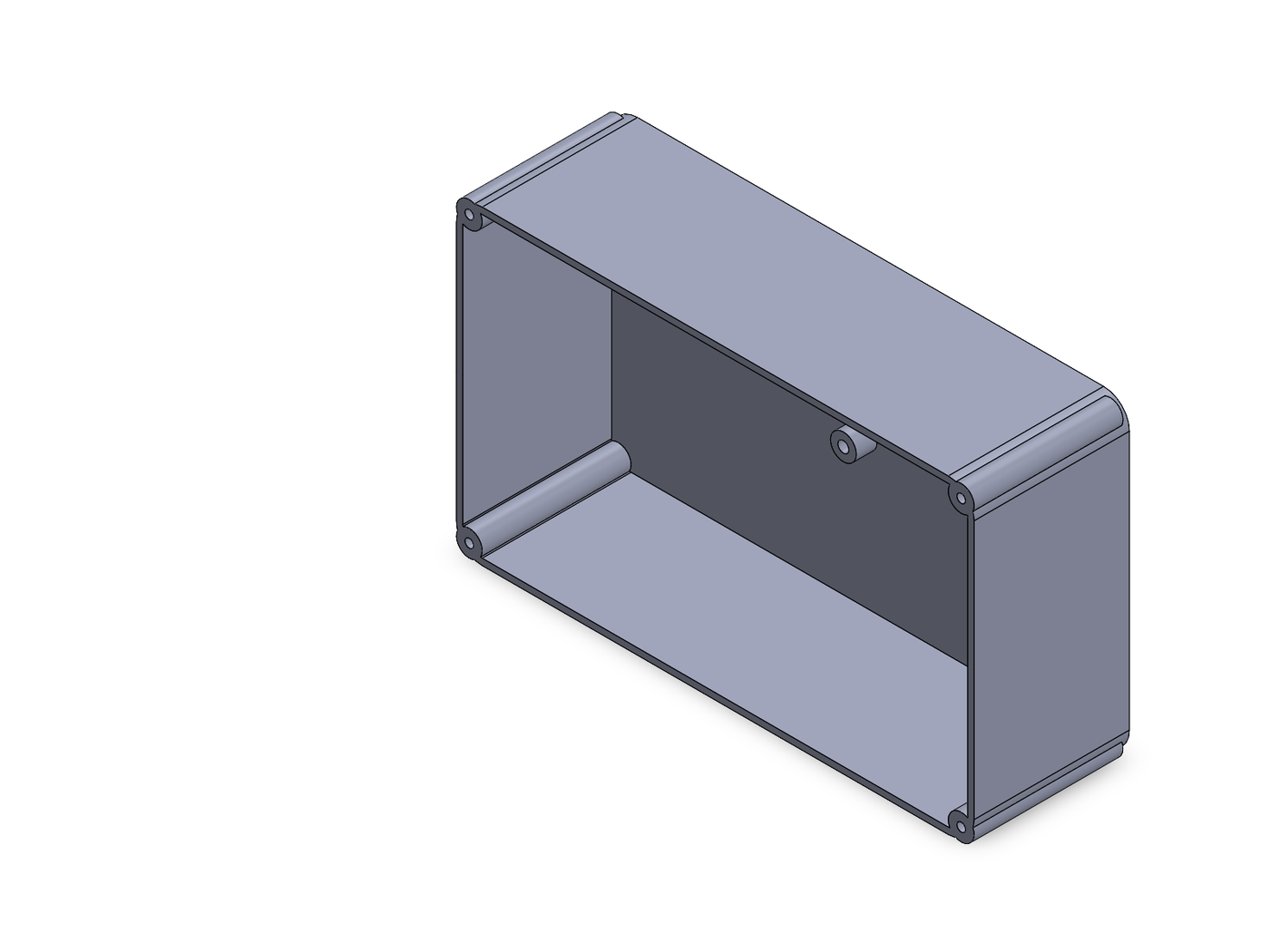
The situation. A die-cast enclosure base has to carry four corner lid-fastener bosses and an earthing boss while staying entirely inside a fixed 200 × 120 × 60 mm envelope — and its own wall thickness is a rule-governed choice, not a stated number.
What happens. CF-WALL-001 (minimum castable wall by process and alloy) gives high-pressure die-cast aluminium a 1.0 mm floor — well below the request’s own 2.5 mm fallback. SM-ENC-002 checks the lid-fastener spacing. Three of these runs found and used CF-WALL-001’s 1.0 mm minimum; one used the 2.5 mm fallback directly. All four stayed inside the dictated envelope.
| CAD system | Measured volume | Note |
|---|---|---|
| SOLIDWORKS 2024 | 160,370.49 mm³ | wall 2.5 mm (fallback) |
| Inventor 2025 | 75,881.45 mm³ | wall 1.0 mm (CF-WALL-001) |
| NX 2306 | 76,717.11 mm³ | wall 1.0 mm (CF-WALL-001) |
| Solid Edge 2024 | 76,675.69 mm³ | wall 1.0 mm (CF-WALL-001) |
12. Consumer products — a tool handle
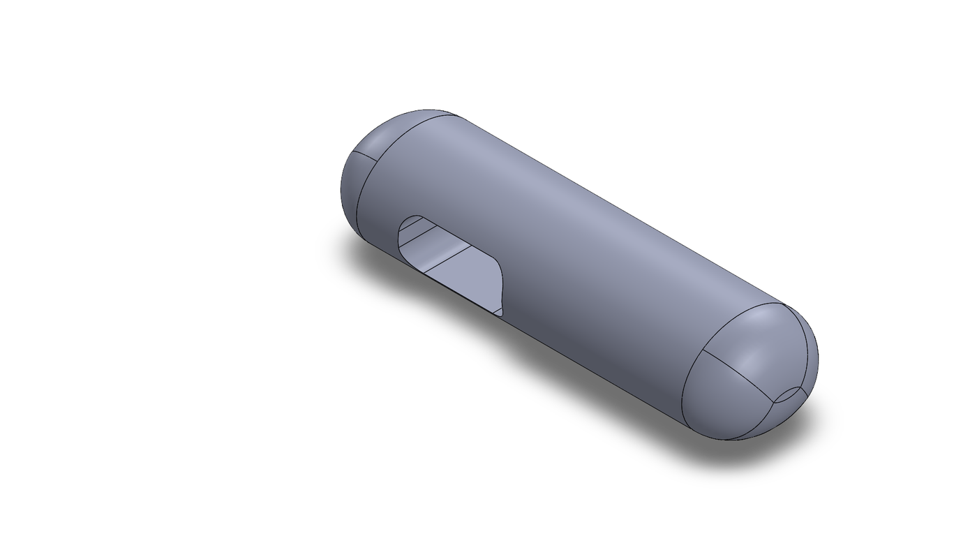
The situation. A moulded power-tool handle’s oval grip has to sit in the ergonomic range, every accessible edge has to be broken, and its trigger slot has to be checked against the rule for gaps that can trap a finger.
What happens. DM-HAND-006 gives a hand tool a narrower grip window than a general hand grip — 30–40 mm rather than 30–45 mm; DM-GEO-017 (sharp external edge on a handled part) sets the 1.0 mm edge break; DM-SAFE-001 is checked against the trigger slot. Two of these runs use 35 mm, the midpoint of DM-HAND-006’s narrower hand-tool window (also this use case’s own stated midpoint); one uses 37.5 mm, the midpoint of the rule’s general range.
| CAD system | Measured volume | Note |
|---|---|---|
| SOLIDWORKS 2024 | 79,590.13 mm³ | grip 35 mm |
| Inventor 2025 | 87,076.72 mm³ | grip 37.5 mm |
| Solid Edge 2024 | 73,983.68 mm³ | grip 35 mm |
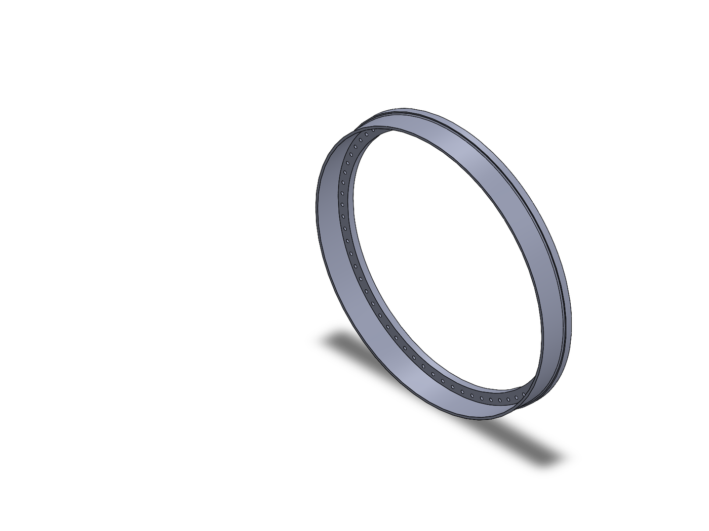
13. Energy — a wind-turbine tower ring flange
The situation. A bolted ring flange joining two tower sections needs its bolt count chosen so the bolt-circle pitch clears the minimum spacing rule without wasting bolts.
What happens. AE-FJ-003 (fastener pitch, minimum 3×D, nominal 4×D) sizes the bolt circle at 69 M36 bolts, a 143.9 mm pitch just above the minimum — a rule written for the aerospace vertical that turned out to be exactly the right generic bolt-spacing check here too. This is the largest and most complex geometry in the set — a big revolved flange and shell stub minus 69 bolt holes.
| CAD system | Measured volume | Note |
|---|---|---|
| SOLIDWORKS 2024 | 248,351,120.32 mm³ | this run did not record a rule id for the bolt count |
| Inventor 2025 | 250,045,547.35 mm³ | bolt count 69, pitch 143.9 mm |
| NX 2306 | 250,045,547.35 mm³ | bolt count 69, pitch 143.9 mm |
| Solid Edge 2024 | 250,045,547.35 mm³ | bolt count 69, pitch 143.9 mm |
14. Defence — a ruggedised equipment box
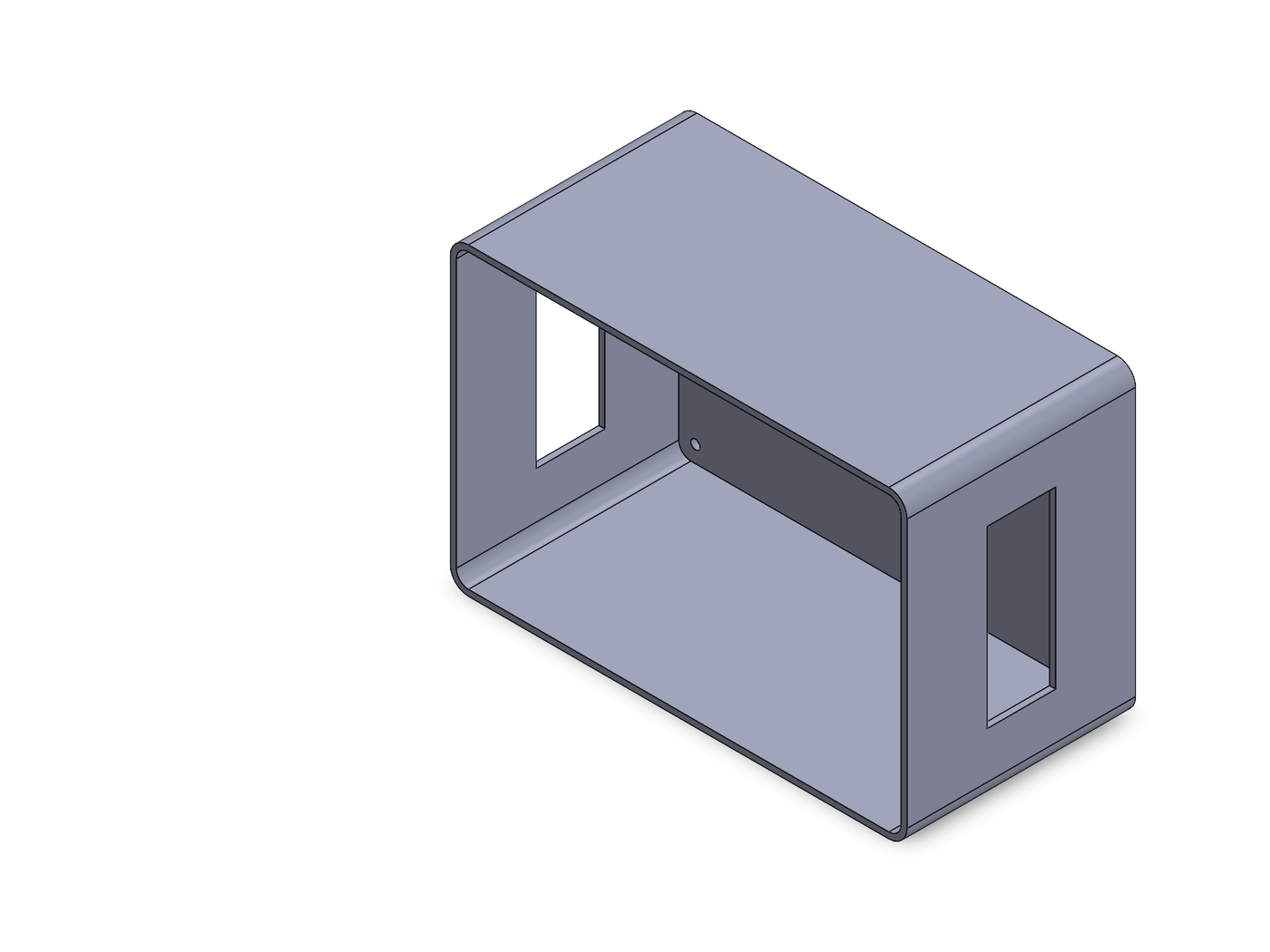
The situation. A ruggedised aluminium equipment box needs a drain hole in every corner of its floor, sized to the rule for a closed section exposed to the weather — and a handle pocket that, in a 4 mm wall, turns out to have to be a through cut-out instead of a recess.
What happens. DM-GEO-014 (closed hollow section without a drain or vent) sets an 8 mm floor for the drain holes; DM-HAND-007 (gloved-hand clearance for a recessed handle, 115×45 mm) backs the handle-pocket clearance the request itself gives as a fallback.
| CAD system | Measured volume | Note |
|---|---|---|
| SOLIDWORKS 2024 | 762,282.97 mm³ | 6 mm drain holes (the request’s own fallback) |
| Inventor 2025 | 761,931.18 mm³ | 8 mm drain holes (DM-GEO-014) |
| NX 2306 | 753,910.15 mm³ | 8 mm drain holes (DM-GEO-014) |
| Solid Edge 2024 | 753,910.15 mm³ | 8 mm drain holes (DM-GEO-014) |
15. How long does this assembly take to load?
The situation. Not every use case here is about a new part — one of the fifteen is a support-desk question: a large assembly is slow to open, and instead of guessing, CoPilot is asked to measure it.
Measure it for me on this CAD session, do not estimate: (1) how long the file takes to OPEN until it is the active document, (2) how long until it is FULLY LOADED with every component resolved, (3) how many components it has in total, how many unique files, and how many came in lightweight / unloaded versus fully resolved, (4) the CAD process's memory before and after, and (5) the machine baseline you measured against. Then tell me the three things that would most reduce the load time for THIS assembly, based on what you measured. Finally close the assembly WITHOUT saving. If the file cannot be opened in this CAD release, say so plainly and quote the CAD's exact words. Do NOT start any CAD application.
End with one line exactly of the form:
RESULT open_ms=<n> fullyload_ms=<n> components=<n> unique_files=<n> resolved=<n> lightweight=<n> memory_before_mb=<n> memory_after_mb=<n> closed=<yes|no>
What happens. CoPilot opens the assembly in the CAD system’s own session, times the two phases separately — active-document open versus every component fully resolved — reads back the component and file counts, and reports the CAD process’s own memory footprint before and after. As one worked example: a public, download-available jet-engine assembly (860 components across 86 unique files) opened as the active document in 14.0 seconds and was fully loaded, every component resolved, in 57.2 seconds. Treat that as one measured example rather than a benchmark — your own assembly’s numbers depend on its own component count, file layout and machine.
Reading the results
A rule-governed dimension is only as good as the choice the model made from the rule — that is why every table above names the choice, not just the number. Agreement is common and worth noticing: use case 1’s exact four-way match, use case 2’s pin hole agreeing to within a millionth of a cubic millimetre, use case 13’s near-exact match among three of the four CAD systems on the hardest geometry in the set. So are genuine differences in the engineering choice, like the wall thickness in use case 11 or the grip diameter in use case 12. Verify a rule-governed dimension the way Verifying Results describes before you commit material to it — that page is not a formality on this one. The design-rule corpus itself is part of your Knowledge Base, alongside anything you index yourself, and the conversational approach used throughout this page is the same one covered in Examples.